
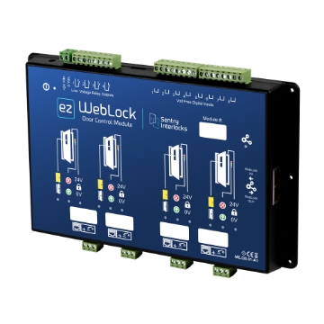
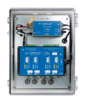
The interface between the Network Bridge and controlled Doors.
| Power Requirements | 24VDC, 1.67 amps max |
| Power Supply | UL Listed, 90-264VAC to 24VDC, 47-63Hz, 1.67A |
| Module Dimensions (H x W x D) | 10.5" x 6.4" x 1.1" (267 x 162 x 28mm) |
| Module Material | Plastic with 6 integrated mounting ears |
| Connections | Network Bridge: Cat 5 U TP Cable Door Accessories: Cat 5 Cable or Wired Leads Door Lock/DPS: Wired Leads |
| LED Indicators | Traffic Light, Door and Lock Status |
| Maximum Number of Doors Modules in Locking Scheme |
25 (each Module handles maximum 4 doors) |
| Maximum Number of Doors Connected/Managed |
Up to 100 |
| Electric Locks | Fail Safe or Fail Secure (upon request) |
| Auxiliary Power Output | 24VDC, 0.7 amps via 2-screw terminal block |
| Door Initial State | Normally unlocked/Normally locked |
| Low Voltage Relay OutPuts | Four Configurable N.O. | N.C. |
| Voltage Free Digital Inputs | Eight |
| Time Delay/Recovery Time | 0 seconds up to 20 minutes |
| Certification | (LVD)2014/35/EU, (EMC)2014/30/EU |
| Warranty | 2-year limited warranty |